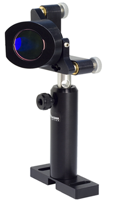
Mounting Option:
Adapter for Beamsplitter 840-0116,
Flipping Mirror/Beamslitter Mount 840-0155-01,
Rod Holder 820-0050-04,
Standard Rod 820-0010-02,
Movable Base 820-0070.
Mounting Option:
Adapter for Round Polarizer 840-0117,
Flipping Mirror/Beamsplitter Mount 840-0155-01M (right hand version),
Rod Holder 820-0050-04,
Standard Rod 820-0010-02,
Movable Base 820-0070.
| 840-0155-01 Flipping Mirror/Beamsplitter Mount - DWG file | |
| 840-0155-01 Flipping Mirror/Beamsplitter Mount - STEP file |
If you would like to review 3D drawings additional software is required. For a quick review of the drawings, we recommend CadFaster - QuickSetup - free software that allows you to view 3D files.
Please follow this link to download the program.
| 840-0155 Flipping Mirror / Beamsplitter Mount
441.09 kB |
- Flip optics in and out of the experiment
- Kinematic design
- Precise and handy angular adjustment in two orthogonal planes
- Stable vertical mounting
- Adjustment range of 9°
- Sensitivity of 3 arcsec
- Max. repeatibility 30 µrad
- Made of black anodized aluminium
- Mirror version available
- Weight 0.09 kg
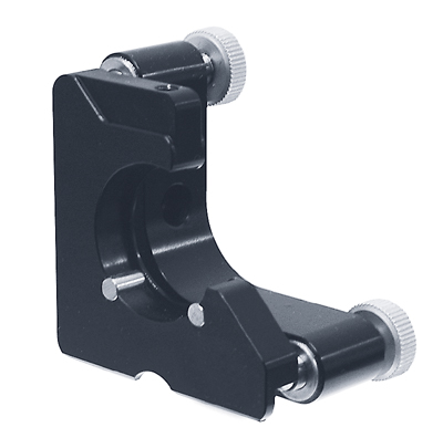
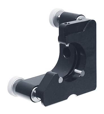
Use Flipping Mount 840-0155 to place optics in and out of the optical scheme. Flip the platform out and back again – it sits on the adjustment screws in a repeated position. Precise alignment of various optical elements to desired angles is done by 2 adjustment screws.
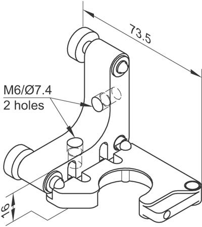
3 seats form 3 kinematic points for definite position of the platform. The seats are made of hardened steel. This increases the service life, as they counter the hardened steel tips of adjustment screws and pivot balls.
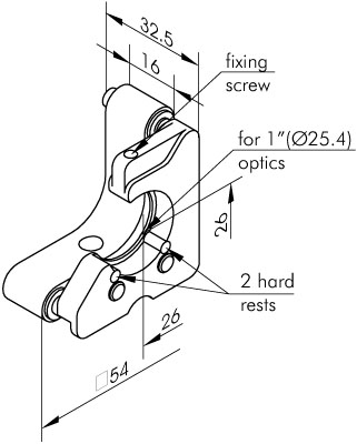
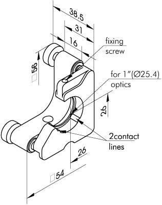
Mount 840-0155 has a 1” mounting hole with Ø24 mm clear aperture. A fixing screw secures the optics against 2 contact lines, which make 2 contact points. To prevent damage to the optics, the tip of the fixing screw is made of plastic. On one side the edge of the optics stays clear. So you can use the optics close to the edge in schemes where you work with a beam very closely situated to another beam.
Ultra-Fine Adjustment Screws 870-0080 come as standard (one screw has its tips modified to form a kinematic point).
Depending on which side you mount the unit, flip the platform either vertically or horizontally. By flipping out vertically, the optics goes beneath the common level of the optical scheme. Still one leg of the base, with a adjustment screw on it, stays up. Yet this would not obstruct the optical path, as it would not when the optics was flipped in. Legs protruding upwards ease access to the adjustment screws, with less risk of obscuring the beam. There is no need to design the legs extended down, so as to clear the space totally.
- Address: Dvarcioniu st. 2B LT-10233 Vilnius, Lithuania
- Phone: (+370) 5 272 99 00
- Fax: (+370) 5 272 92 99
- E-mail: [email protected]